


Welcome to inquire:+86-18031760999


 News

— News —
News
Manufacturing process description of alloy pipe fittings
Click:
Time:2026-10-16 15:18:19
- 一、
Manufacturing Process Description of Alloy Pipe Fittings of Hebei Hongcheng Pipe Industry Co., Ltd.
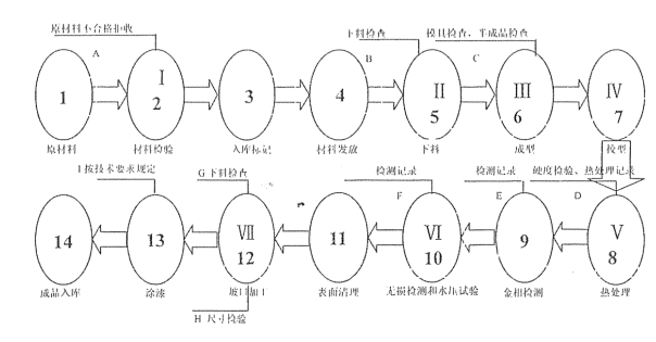
1. Manufacturing Process Flow of P91 Pipe Fittings
- Note: I, II, III, IV, V, VI, VII are control links; A, B, C, D, E, F, G, H, I are control points; 1, 2, 3, 4, 5, 6, 7, 8, 9, 10, 11, 12, 13, 14 are process numbers.
- 2. Process Control
- 2.1 Material Re-inspection
- 2.1.1 Our company possesses multiple professional testing equipment for materials and finished products. Newly arrived materials undergo the following re-inspections according to relevant standards:
- 1) Spectrometer analysis of the material spectra;
- 2) Thickness gauge measurement of pipe and plate wall thickness;
- 3) Caliper and measuring tape measurement of pipe outer diameter and end roundness deviation;
- 4) Visual inspection of pipes (piece by piece) for defects such as pits, cracks, scars, overlapping layers, and smoothness without oxide scale; the appearance should meet the requirements of relevant standards: checking for defects such as waviness, wrinkles, shrinkage cavities, slag inclusions, sand adhesion, folds, incomplete welds, overlapping layers, corrosion, sharp scratches, pits (not exceeding 1.5mm), and depressions (not exceeding 5% of the pipe circumference and not greater than 40mm).
- 5) Randomly sample one piece from each batch for mechanical property re-inspection using a universal testing machine;
- 6) Randomly sample one piece from each batch for rapid analysis to determine the chemical composition of the material;
- 7) Perform 100% UT (Underwriters Test and Finish) non-destructive testing on all incoming raw materials according to ASTM (American Society for Testing and Materials) requirements to ensure the raw materials are free of cracks and delamination.
- 8) Perform hardness testing on each piece: the hardness at any point should meet the corresponding standard requirements.
- 9) The inspection results of all materials should correspond to the quality certificate of the raw materials; materials without markings, batch numbers, quality certificates, or with incomplete quality certificates cannot be used.
- 2.1.2 After the materials pass the inspection by the testing department, an inspection certificate of conformity will be issued, allowing the materials to proceed to the next process, and a material re-inspection record will be filled out. (See the High-Pressure Pipe Fittings Physical and Chemical Inspection Control Chart and Pressure Pipe Fittings Material Management Quality Control Chart for details)
- 2.2 Cutting and Blanking
- 2.2.1 Before cutting, the technical department selects materials with sufficient allowance based on the finished product's dimensions and processing method, considering factors such as thinning, deformation, and various processing losses that may occur during production. If necessary, a template is made, and the production department cuts the material according to the template's dimensions.
- 2.2.2 During cutting and blanking, the outer diameter, wall thickness, material, pipe number, furnace batch number, and pipe fitting blank serial number of the raw materials are clearly marked and transferred according to design requirements. The markings are done using low-stress steel stamping and paint spraying, and the operation details are recorded on the production process flow card to ensure material traceability during processing.
- 2.2.3 After the first piece is cut, the operator conducts a self-inspection and reports it to the testing center for specialized inspection. Only after passing inspection can other pieces be cut, and each piece is inspected and recorded. For products that fail to meet the cutting standards, a non-conformity notification form must be filled out. The decision on whether the material can be processed will be made after review and approval by the technical department; otherwise, the material should be scrapped.
- 2.3 Forming
- 5.3.1. The pressing and forming process of pipe fittings is a crucial process.
- 5.3.2. Clean debris from the jig, and check the electrical circuits, oil circuits, and trolley for proper functioning; ensure sufficient oil and that the electrical circuits are intact.
- 5.3.3. During the forming process, strictly control the forming speed and employ a multi-extrusion forming process on the press.
- 2.4 Welding
- 2.4.1 For steel plate butt-welded pipe fittings, welding work must be performed by professional welders with many years of welding experience. Appropriate welding procedure qualification must be performed according to requirements, and mechanical property tests must be conducted on the weld. Welding production is carried out under strict process specifications. The welding process adopts qualified welding procedure qualification, which should comply with the provisions of relevant standards such as JB4708-2008. Welders are also qualified according to this standard. If a welder's welding work does not match their certified work, welding is prohibited. During welding, a quality assurance engineer will monitor and measure the stop points and witness points of the welding process to ensure that this critical process is free of defects and problems.
- 2.4.2 The welding process must strictly follow the company's "Welding Process Guidance Card." First, the welding electrodes must be dried according to the electrode quality certificate. After drying, the electrodes are placed in an insulated box for later use. Argon arc welding is used for the root pass, followed by manual arc welding for the fill and cover passes. During the root pass, the pipe is filled with argon for protection to prevent overheating and oxidation. The interpass temperature must be controlled below 200℃. During welding, the overlaps between passes must be ground with a hammer or grinding wheel, and weld slag and spatter must be cleaned.
- 2.4.3 Carbon steel is not allowed as a ground wire during welding. The ground wire must be securely fixed to the workpiece; spot welding is prohibited. When rolling steel plates, the rolling roller surface should be covered with a material free of iron ions. Tools that may cause iron ion contamination must not be used during assembly. 2.4.4 When performing pickling and passivation, pickling of carbon steel components should be avoided as much as possible. If it cannot be avoided, protective measures must be taken for the carbon steel components beforehand.
- 2.4.4 Welded pipe fittings should undergo post-weld heat treatment to ensure that the welded joint has mechanical properties and other technical indicators similar to the base material.
- 2.4.5 The welds of welded pipe fittings must undergo 100% radiographic inspection, and a radiographic inspection report must be provided to you.
- (See the welding quality control flowchart for details)
- 2.5 Heat Treatment Process
- 2.5.1 Heat Treatment
- A. Pipe fittings need to undergo normalizing and tempering heat treatment according to the standard specifications. Recorded curves and heat treatment reports should be included in the product archive as part of the delivery documentation.
- 2.5.2 For P91 pipe fitting semi-finished products, heat treatment should be carried out strictly in accordance with the heat treatment system specified in the relevant standards.
- 2.5.3 Before heat treatment, ensure that the heat treatment furnace is clean and free of oil, ash, rust, and other metals different from the material being treated.
- 2.5.4 All heat-treated pipe fittings shall be subjected to hardness testing individually, and a corresponding hardness report shall be provided.
- 2.5.5 Workpieces shall be evenly placed in the furnace, all within the effective heating zone, with a minimum spacing of 200mm.
- 2.5.6 The heating equipment is a 4m*20m*2.5m gas-fired furnace. A test piece shall be placed in each furnace.
- 2.5.7 Preparation: Carefully inspect the equipment, wires, thermocouples, etc., and only start the machine after confirming that the equipment is normal and the connections are reliable.
- 2.5.8 Temperature difference control: For each furnace cycle, strive for uniform temperature on the inner and outer walls of all pipes. During constant temperature operation, the temperature difference between any two measuring points within the heating range should be less than 50℃.
- 2.5.9 Temperature measuring point arrangement: The installation position of thermocouples should be based on the principle of ensuring accurate, reliable, and representative temperature measurements. For horizontal pipes, temperature measuring points should be symmetrically arranged vertically; for zoned temperature control, the arrangement of thermocouples should be adapted to the heating device.
- 2.5.10 Temperature Measurement Requirements: Temperature measurement during heat treatment must be accurate and reliable, and automatic temperature recording should be used. All instruments, thermocouples, and accessories used should be calibrated and verified according to metrological requirements.
- 2.5.11 Temperature Measurement Method: Thermocouples, infrared thermometers.
- 2.5.12 Recording Method: Temperature recording table and heat treatment curve.
- Weld Heat Treatment: Heat treatment using tracked heating elements.
- All heat-treated pipe fittings should undergo hardness testing individually, and a corresponding hardness report should be provided.
- (See the heat treatment quality assurance system diagram for details)
- 2.6 Machining and Beveling
- Beveling of pipe fittings is performed using mechanical cutting. Our company has over 20 machining equipment, including various lathes and power heads, and can process various thick-walled pipes using double V-shaped or single V-shaped beveling, as well as internal and external beveling, according to the relevant standards specified in the order and the buyer's requirements. Our company can perform beveling machining entirely according to standards and technical requirements, ensuring that the pipe fittings are easy to operate and weld during the welding process.
- 2.7 Surface Treatment
- 2.7.1 After machining, the inner and outer surfaces of carbon steel and alloy pipe fittings shall be sandblasted to remove rust. After sandblasting and grinding, the inner and outer surfaces of the pipe fittings shall be smooth and exhibit a metallic luster. Rust, oxide scale, and other defects are not permitted on the pipe fittings.
- 2.8 Finished Pipe Fittings Inspection
- 2.8.1 All pipe fittings shall undergo visual inspection. Visual inspection shall be performed piece by piece and shall meet the following requirements: Defects such as scale, cracks, folds, and slag inclusions that do not penetrate the minimum wall thickness are permitted to be removed by grinding. The remaining wall thickness after removing the defects shall not be less than the minimum wall thickness. Otherwise, the pipe fitting shall be scrapped.
- 2.8.2 Before leaving the factory, pipe fittings shall undergo various tests according to the standards corresponding to the order requirements or the requirements specified by the buyer. All tests shall be performed by qualified professionals recognized by the State Bureau of Technical Supervision.
- 2.8.3 Finished pipe fittings shall undergo the following tests:
- 1) All pipe fittings shall undergo geometric dimensional testing according to the specified relevant standards. 1) The allowable deviations for the inspection items shall comply with relevant standards.
- 2) All carbon steel and alloy pipe fittings shall undergo 100% MT inspection on a piece-by-piece basis. For microcracks with a depth not exceeding 0.8mm detected by MT, grinding removal is permitted. Otherwise, the pipe fitting shall be scrapped.
- 3) All weld bevels of pipe fittings shall undergo 100% MT or 100% PT inspection, in accordance with JB/T4730-2005.
- 2.8.4 Provide users with various non-destructive testing reports (metallographic structure, heat treatment report, UT, etc.), geometric dimension inspection records, and product quality certificates for the pipe fittings.
-
10-162026
Reco Manufacturing process description of alloy pipe fittings
一、Manufacturing Process Description of Alloy Pipe Fittings of Hebei Hongcheng Pi
-
10-052026
How to choose a domestic prefabricated pipe manufacturer
As domestic industrial pipeline engineering evolves towards specialization and s
-
10-022026
Reco How to choose reliable alloy steel pipes? Recommended high-quality manufacturers of A335P9/P91/P92.
A335P91 and A335P92 Alloy Steel Pipes: A Comprehensive Guide to Selection+86 131
-
10-022026
Detailed Explanation of T92/P92 Martensitic Heat-Resistant Steel Grades
P92 belongs to the American standard martensitic heat-resistant steel, conformin
-
04-012021
The downstream industries of the alloy steel pipe market are already gearing up for large-scale preparations
With the implementation of more micro-stimulus measures, the real economy has been picking up; as the country’s various supporting policies and measures to support micro-stimulus are implemented, and
-
04-012021
Alloy steel pipe merchants' sustenance on the micro-stimulus policy
For a period of time, the price of alloy steel pipes has fallen sharply. Analyzing the main factors of price drops is not due to the so-called market oversupply, but the foresight of the world's minin

Site navigation

微信
Contact us
China Hebei Hongcheng Pipe Industry Co., Ltd.
Tel:+86-317-6855557
Fax:+86-317-6396578
Phone:+86-18031760999
Mailbox:hbhctg@163.com
Address:Wuliyao , Yanshan County, Cangzhou City, Hebei Province, China
All Rights Reserved:China Hebei Hongcheng Pipe Industry Co., Ltd.
All Rights Reserved:English-China Hebei Hongcheng Pipe Industry Co., Ltd.
《The People's Republic of China Telecommunications and Information Service Industry Business License》
Technical Support:
Links:

